Introduction
With the release of Gravwell 5.0, my boss, asked me to write a blog post on making a simple “Hello World!” flow. Something to get folks started.

Pictured: The boss conducting a "Productivity Audit"
The problem, however, is that a “Hello World!” flow isn’t all that interesting or informative. In fact, it’s a single node:
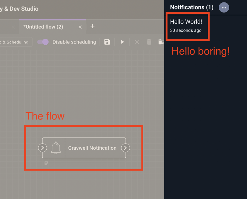
Whoop dee doo
Instead, I decided to expand upon this post a bit, and created a larger flow that would flex a bit more of the new flows system but still technically produce a “Hello World!”, just as the boss asked.
To that end, I present a masterclass in “interpreting what the boss wants” – a fully pipelined, 5-stage MIPS CPU running a “Hello World!” program, implemented entirely in Gravwell Flows.
Overview
This “Hello World!” flow is actually a set of five flows, representing the five stages of a MIPS CPU pipeline (detailed below). It has a small memory, program counter, register file, and even a simple memory mapped terminal (operated by a sixth flow) that outputs over HTTP to a terminal program. All of the state is implemented using Gravwell resources, and the flows interact with one another via pipeline registers (also using Gravwell resources).
Some other highlights of the Flow CPU:
- Speed: A face melting .016 Hz
- Memory: 64 bytes (4 bytes memory mapped as a terminal)
- Instruction set: 6 instructions from the MIPS ISA
- Load byte
- Store byte
- Jump
- Branch if Equal
- Add Immediate Unsigned
- No Operation (NOP)
Let’s walk through each part of the CPU.
The memory and program
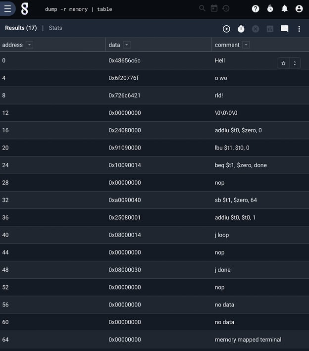
The CPU has a 64 byte memory, implemented as a Gravwell resource. We can look at it by issuing a simple query to dump the contents of the resource, shown above. MIPS is byte addressable and word aligned. The first 4 words are a hard coded “Hello World!” string, and our program begins at address 16.
The program is a simple loop that copies memory, starting at the beginning of the hard coded string, to the memory mapped terminal at address 64. Afterwards it falls into a stop loop. The instructions were simply hand encoded as a CSV and imported into Gravwell.
The CPU
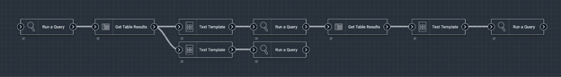
The CPU is made up of five flows, each representing a pipeline stage. MIPS has five stages – instruction fetch, instruction decode, execute, memory, and writeback. While we have all five stages implemented here, it’s worth noting that this CPU isn’t really pipelined – there is no concurrent execution of stages, and as such we could have collapsed this entire flow into a single flow. But that isn’t fun, and the boss hasn’t asked what I’ve been doing all day yet, so we continue.
Instruction Fetch
This first stage (flow) reads from the program counter resource, extracts the PC value into a flow variable, and uses it in a template to read from the memory resource at that address. It then inserts the read value into a pipeline resource and updates the PC for the next instruction.
Simple…
Instruction Decode

Our CPU supports six instructions. In the decode stage, we simply break the instruction into the various possible components of a MIPS instruction. UC Berkeley has a great overview of the MIPS instruction encodings.
Execute
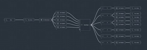
In the execute stage, Gravwell flows really show their utility. The flow extracts all of the instruction parts (opcode, register locations, etc.) into flow variables, and has six execution paths, one for each of our six instructions. In a Gravwell flow, if a node fails to execute (in this case because we have an “if” node comparing the instruction opcode), then all nodes downstream of that node won’t be executed. This allows us to simply construct all six instruction execution flows together, knowing that only one will execute.
Memory
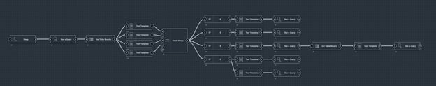
Similar to the execute stage, the memory stage has several possible paths to execute (load byte, store byte, etc.). Instructions that don’t use memory, such as “add immediate” also have a path that just moves that data along to the next stage.
Writeback

Finally, the writeback stage updates the register file if necessary. Simple!
What are all those sleep nodes?
Good eye! You may have noticed that all but the first stage in this example have a sleep node at the beginning of the flow. That’s because the fastest Grawell flows can execute is every minute, and while the flows do execute in parallel, they aren’t parallel in the sense that a CPU is (clock edge triggered state updates). To make sure data moves across the CPU in the expected order, we add a sleep to each of the latter stages to stagger their execution slightly. It’s a hack, but well so is this whole example.
The terminal
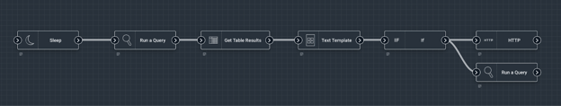
The terminal is a combination of a flow that reads from the memory mapped I/O location, clearing the value if data has been written, and writing the written value to a simple webserver using an HTTP node and an HTTP POST. The webserver simply writes any data it’s given.
Giving it a try
The entire set of flows, resources, and the terminal program are available here if you want to try this out for yourself. Simple load the flows and resources, and schedule each flow to run every minute.
Conclusion
Gravwell Flows are an incredibly powerful way to automate workflows, reports and alert, and even build turing complete machines to annoy the boss.
<insert more marketing speak here>
Try Community Edition.